
Option C - Imaging
Question 1
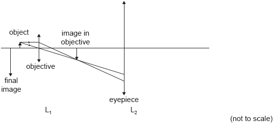
SLPaper 3The diagram is a partially-completed ray diagram for a compound microscope that consists of two thin converging lenses. The objective lens L1 has a focal length of cm. The object is placed cm to the left of L1. The final virtual image is formed at the near point of the observer, a distance of cm from the eyepiece lens L2.
Two converging lenses are used to make an astronomical telescope. The focal length of the objective is cm and that of the eyepiece is cm. The telescope is used to form a final image of the Moon at infinity.
The diagram is a partially-completed ray diagram for a compound microscope that consists of two thin converging lenses. The objective lens L1 has a focal length of cm. The object is placed cm to the left of L1. The final virtual image is formed at the near point of the observer, a distance of cm from the eyepiece lens L2.
Two converging lenses are used to make an astronomical telescope. The focal length of the objective is cm and that of the eyepiece is cm. The telescope is used to form a final image of the Moon at infinity.
State what is meant by a virtual image.
Show that the image of the object formed by is 12 cm to the right of .
The distance between the lenses is 18 cm. Determine the focal length of L_{2}.
On the diagram draw rays to locate the focal point of L2. Label this point F.
Explain why, for the final image to form at infinity, the distance between the lenses must be 87.5 cm.
The angular diameter of the Moon at the naked eye is rad.
Calculate the angular diameter of the final image of the Moon.
By reference to chromatic aberration, explain one advantage of a reflecting telescope over a refracting telescope.
Question 2
HLPaper 3Explain the cause of the radio-frequency emissions from a patient’s body during nuclear magnetic resonance (NMR) imaging.
Outline how a gradient field allows NMR to be used in medical resonance imaging.
Identify one advantage of NMR over ultrasound in medical situations.
Question 3
HLPaper 3The table shows the speed of ultrasound and the acoustic impedance for different media.
| speed of ultrasound | acoustic impedance | |
|---|---|---|
| air | ||
| gel | ||
| skin |
The fraction F of the intensity of an ultrasound wave reflected at the boundary between two media having acoustic impedances Z1 and Z2 is given by
.
Outline how ultrasound is generated for medical imaging.
Describe one advantage and one disadvantage of using high frequencies ultrasound over low frequencies ultrasound for medical imaging.
Suggest one reason why doctors use ultrasound rather than X-rays to monitor the development of a fetus.
Calculate the density of skin.
Explain, with appropriate calculations, why a gel is used between the transducer and the skin.
Question 4
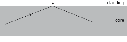
SLPaper 3A ray of light travelling in an optic fibre undergoes total internal reflection at point P.
 The refractive index of the core is 1.56 and that of the cladding 1.34.
The input signal in the fibre has a power of 15.0 mW and the attenuation per unit length is 1.24 dB km.
Calculate the critical angle at the core-cladding boundary.
The use of optical fibres has led to a revolution in communications across the globe. Outline two advantages of optical fibres over electrical conductors for the purpose of data transfer.
Draw on the axes an output signal to illustrate the effect of waveguide dispersion.
Calculate the power of the output signal after the signal has travelled a distance of 3.40 km in the fibre.
Explain how the use of a graded-index fibre will improve the performance of this fibre optic system.
Question 5
SLPaper 3The refractive index of a material is the ratio of the speed of light in a vacuum , to the speed of light in the material or .
The speed of light in a vacuum is 2.99792 × 10^8 m s^-1. The following data are available for the refractive indices of the fibre core for two wavelengths of light:
| Wavelength | Refractive index |
|---|---|
| 1.45061 | |
| 1.45059 |
Outline the differences between step-index and graded-index optic fibres.
Determine the difference between the speed of light corresponding to these two wavelengths in the core glass.
An input signal to the fibre consists of wavelengths that range from 1299 nm to 1301 nm. The diagram shows the variation of intensity with time of the input signal.
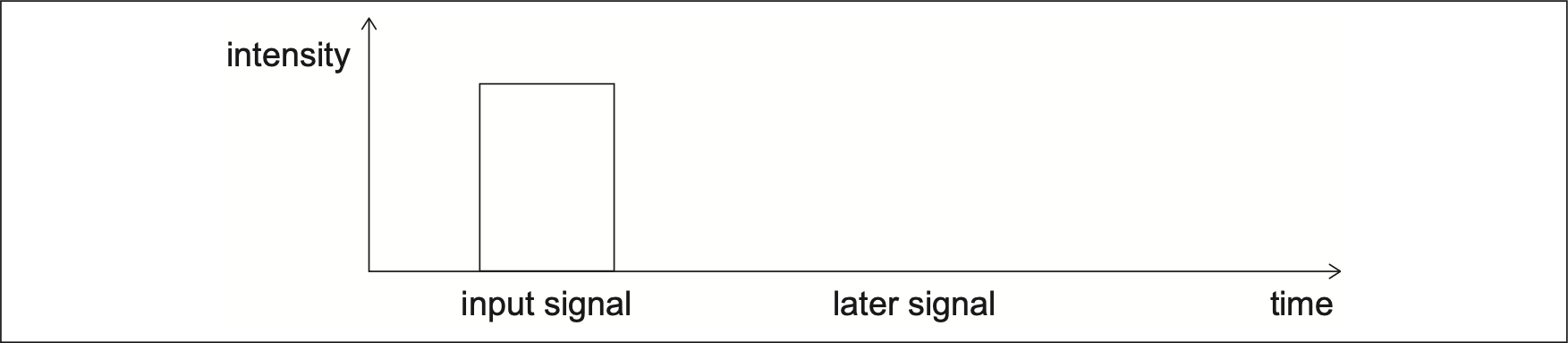
Sketch, on the axes, the variation of signal intensity with time after the signal has travelled a long distance along the fibre.
Explain the shape of the signal you sketched in .
A signal consists of a series of pulses. Outline how the length of the fibre optic cable limits the time between transmission of pulses in a practical system.
Question 6
HLPaper 3An X-ray beam, of intensity , is used to examine the flow of blood through an artery in the leg of a patient. The beam passes through an equal thickness of blood and soft tissue.
 The thickness of blood and tissue is 5.00 mm. The intensity of the X-rays emerging from the tissue is and the intensity emerging from the blood is .
The following data are available.
The thickness of blood and tissue is 5.00 mm. The intensity of the X-rays emerging from the tissue is and the intensity emerging from the blood is .
The following data are available.
- Mass absorption coefficient of tissue = 0.379 cmg
- Mass absorption coefficient of blood = 0.385 cmg
- Density of tissue = 1.10 × 10kg m
- Density of blood = 1.06 × 10kg m
Show that the ratio is close to 1. a(i).
State and explain, with reference to your answer in , what needs to be done to produce a clear image of the leg artery using X-rays.
In nuclear magnetic resonance (NMR) protons inside a patient are made to emit a radio frequency electromagnetic radiation. Outline the mechanism by which this radiation is emitted by the protons.
Question 7
HLPaper 3An X-ray beam of intensity is incident on lead. After travelling a distance through the lead the intensity of the beam is reduced to .
The graph shows the variation of with .
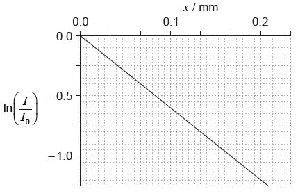
Show that the attenuation coefficient of lead is 60 cm.
A technician operates an X-ray machine that takes 100 images each day. Estimate the width of the lead screen that is required so that the total exposure of the technician in 250 working days is equal to the exposure that the technician would receive from one X-ray exposure without the lead screen.
Question 8
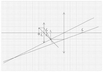
SLPaper 3Outline the meaning of normal adjustment for a compound microscope.
Sketch a ray diagram to find the position of the images for both lenses in the compound microscope at normal adjustment. The object is at O and the focal lengths of the objective and eyepiece lenses are shown.
Question 9
HLPaper 3The linear attenuation coefficient for tissue is .
The fluid in the bowel has a similar linear attenuation coefficient as the bowel surface. Gases have much lower linear attenuation coefficients than fluids. Explain why doctors will fill the bowel with air before taking an X-ray image.
Question 10
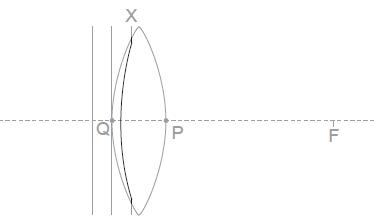
SLPaper 3The diagram shows planar wavefronts incident on a converging lens. The focal point of the lens is marked with the letter F.
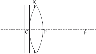
Wavefront X is incomplete. Point Q and point P lie on the surface of the lens and the principal axis.
On the diagram, sketch the part of wavefront that is inside the lens.
On the diagram, sketch the wavefront in air that passes through point P. Label this wavefront Y.
Explain your sketch in .
Two parallel rays are incident on a system consisting of a diverging lens of focal length 4.0 cm and a converging lens of focal length 12 cm.
 The rays emerge parallel from the converging lens. Determine the distance between the two lenses.
