
Topic 11 - Induction, Alternating Currents, & Capacitance
Question 1
HLPaper 1A capacitor is charged by a constant current of 2.5 μA for 100 s. As a result the potential difference across the capacitor increases by 5.0 V.
What is the capacitance of the capacitor?
Question 2
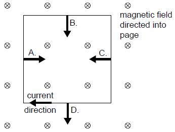
HLPaper 1A conducting square coil is placed in a region where there is a uniform magnetic field.The magnetic field is directed into the page. There is a clockwise current in the coil.
What is a correct force that acts on a side of the coil?
Question 3
HLPaper 1The current I flowing in loop A in a clockwise direction is increasing so as to induce a current both in loops B and C. All three loops are on the same plane.
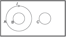
What is the direction of the induced currents in loop B and loop C?
| Loop B | Loop C | |
|---|---|---|
| A. | clockwise | clockwise |
| B. | clockwise | anti-clockwise |
| C. | anti-clockwise | clockwise |
| D. | anti-clockwise | anti-clockwise |
Question 4
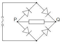
HLPaper 1The input to a diode bridge rectification circuit is sinusoidal with a time period of 20 ms.
 Which graph shows the variation with time of the output voltage between X and Y?

Question 5
HLPaper 1The graph shows the variation of an alternating current with time in a resistor.
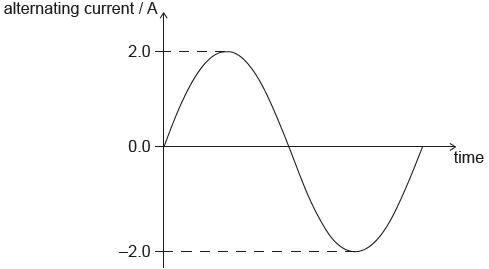
What is the average power dissipated in the resistor?
Question 6
HLPaper 2The diagram shows a sketch of an ideal step-down transformer.
 The number of turns in the primary coil is 1800 and that in the secondary coil is 90.
State Faraday's law of induction.
Explain, using Faraday’s law of induction, how the transformer steps down the voltage.
The input voltage is V. Calculate the output voltage.
Outline how energy losses are reduced in the core of a practical transformer.
Step-up transformers are used in power stations to increase the voltage at which the electricity is transmitted. Explain why this is done.
Question 7
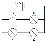
HLPaper 2Three identical light bulbs, X, Y and Z, each of resistance 4.0 Ω are connected to a cell of emf 12 V. The cell has negligible internal resistance.

When fully charged the space between the plates of the capacitor is filled with a dielectric with double the permittivity of a vacuum.
The switch S is initially open. Calculate the total power dissipated in the circuit.
The switch is now closed. State, without calculation, why the current in the cell will increase.
The switch is now closed. Deduce the ratio .
The cell is used to charge a parallel-plate capacitor in a vacuum. The fully charged capacitor is then connected to an ideal voltmeter.
The capacitance of the capacitor is and the reading of the voltmeter is .
Calculate the energy stored in the capacitor.
Calculate the change in the energy stored in the capacitor.
Suggest, in terms of conservation of energy, the cause for the above change.
Question 8
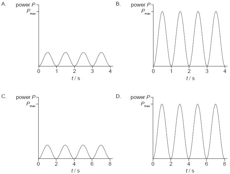
HLPaper 1The graph shows the variation of the peak output power P with time of an alternating current (ac) generator.
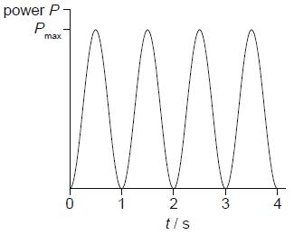
Which graph shows the variation of the peak output power with time when the frequency of rotation is decreased?
Question 9
HLPaper 1Why are high voltages and low currents used when electricity is transmitted over long distances?
Question 10
HLPaper 1An alternating supply is connected to a diode bridge rectification circuit.
The conventional current in the load resistor
