All topics

An ideal transformer has a primary coil with turns and a secondary coil with turns. The electrical power input to the primary is . Which of the following is the power output from the secondary?

This question is about alternating current. The graph shows the variation with time t of the output voltage V of an ac generator of negligible internal resistance. 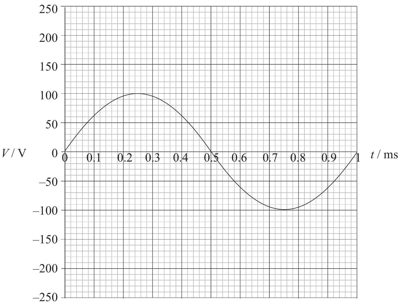 A resistor of resistance 25 Ω is connected across the output of the generator.

Calculate the rms value of the current in the resistor.

Calculate the average power dissipated in the resistor.

Calculate the power dissipated in the resistor at 0.40 ms.

The frequency of rotation of the generator coil is now doubled. Sketch, using the axes in , the variation with t of the new output voltage V.

An alternating current is sinusoidal and has a maximum value of 1.5 A . What is the approximate value of the root mean squared (rms) current?

The primary of an ideal transformer has 1000 turns and the secondary 100 turns. The current in the primary is 2 A and the input power to the primary is 12 W .
Which one of the following about the secondary current and the secondary power output is true?
| secondary current | secondary power output | |
|---|---|---|
| A. | 20 A | 12 W |
| B. | 0.2 A | 12 W |
| C. | 0.2 A | 120 W |
| D. | 20 A | 120 W |

A capacitor is charged by a constant current of for 100 s . As a result the potential difference across the capacitor increases by 5.0 V .
What is the capacitance of the capacitor?

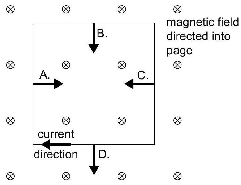
A conducting square coil is placed in a region where there is a uniform magnetic field. The magnetic field is directed into the page. There is a clockwise current in the coil.
What is a correct force that acts on a side of the coil?

A ring of area is in a uniform magnetic field . Initially the magnetic field is perpendicular to the plane of the ring. The ring is rotated by about the axis in time .
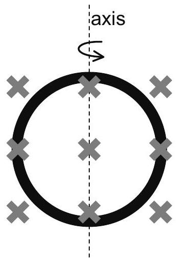
What is the average induced emf in the ring?

The design of a nuclear power station includes an electrical generator. The function of the generator is to convert

This question is about the growth of an electric current in a coil. When a coil is connected to a d.c. power supply the current in the coil does not change instantaneously but takes a finite time to reach a steady value. For a given supply the final, steady value of the current is determined by the resistance (R) of the coil. In the diagram below a coil is connected to a d.c. supply of emf 4.0 V. [Image of circuit diagram] When the switch S is closed an electronic timer is started and the current I is recorded at different values of the time t. The results are shown in the table below. (Uncertainties in measurement are not shown). | t / s | 0 | 0.2 | 0.6 | 1.0 | 1.4 | 1.8 | 2.0 | | :---: | :--- | :--- | :--- | :--- | :--- | :--- | :--- | | I / A | 0 | 0.8 | 1.6 | 1.9 | 2.0 | 2.0 | 2.0 |

Plot a graph of current against time.

What is the steady state value of the current?

Determine the value of the resistance R of the coil.

By drawing a tangent to the curve at the point (0,0) on your graph, determine the time it would take for the current to reach its steady state value if it were to continue changing at its initial rate. (This time is known as the time constant of the coil).

The initial rate at which the current in the coil changes is given by the expression V/L where V is the value of the supply potential and L is a property of the coil known as its inductance. Show that the time constant τ for the coil is given by the expression τ = L/R

Determine the value of the inductance L of the coil.

The kilowatt-hour is equivalent to approximately
